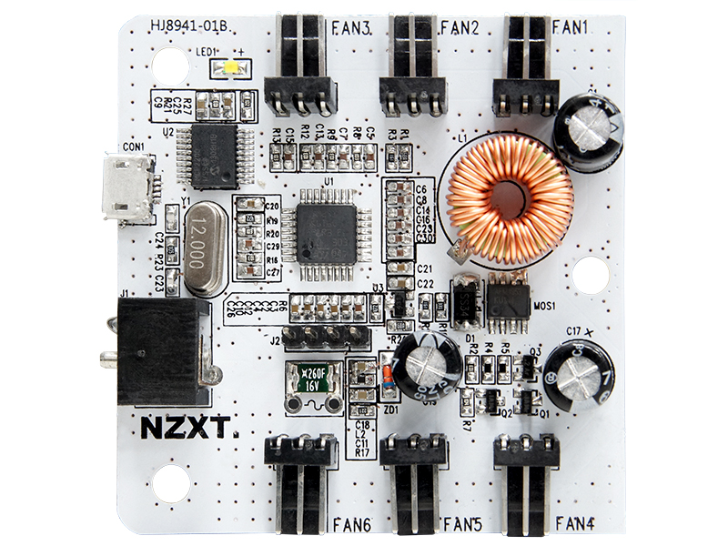
I was looking for a digital chassis fan controller for my main rig and stumbled upon the NZXT GRID+ digital fan controller. As my current motherboard does not support non-PWM chassis fan speed control via software, I looked for a software based solution that I could stick inside my case to manually control the fan speeds as the Corsair AF120 fans in my rig are noticeably noisy even when my system is idling (probably because my motherboard is driving them at 1100RPM 24/7). I personally find slot and drive bay based rheobus/digital controllers unappealing as they somewhat alter the outer design of my case. LinusTechTips had some pretty decent things to say about the NZXT GRID+ so I decided to drop the 35USD and pick it up from a local reseller.
It arrived yesterday in some standard packaging. However, it wasn’t until I had setup the drivers and software that I realized the controller had a ton of limitations. Specifically :
- It’s a 6 port, single channel controller. It can detect the RPM pulse signal from all 6 ports but speed adjustments are applied equally to all ports.
- Speed adjustments are percentage based (with 5% increments) and are limited to between 40-100% (firmware limit).
- You can’t turn off the fans completely.
- The provided NZXT CAM software is an absolute piece of garbage. Cloud PC fan speed management? A ‘companion’ for my PC? Remote fan speed control software via a mobile app? The process is constantly between 1.5%-30% of CPU usage on my OCed i7-2600k and it’s memory usage hovers between 120-200MB’s. I wanted a fan speed controller for my PC, not an escort.
- The user reviews at Newegg, Amazon as well as NZXT’s own support website highlight the issues with their provided ‘CAM’ software and it ranges from system stability issues, resource hogging and poor sensor readouts.
Not wanting to toss the device away, I decided to see if I could reverse engineer their drivers and come up with my own control software. It turned out pretty okay.
Figuring Out the Drivers
The first thing I did was to poke around my Device Manager to see what drivers the CAM software had installed. I was pleasantly surprised to find this :
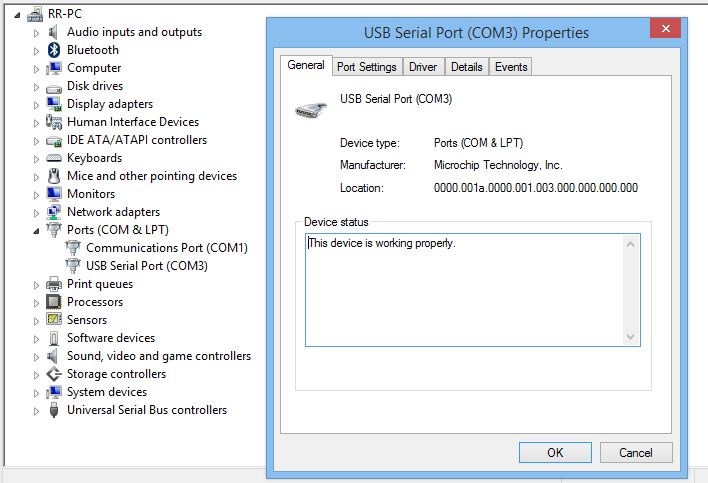
It had installed a ‘USB Serial Port’ COM device. This meant it was probably using some sort of USB-Serial adapter chip. After some further poking around in the CAM software folder, I noticed a folder called ‘GridChipsetDriver’ next to something called the Kraken driver (which I’m guessing is for their Kraken CPU cooler line — something that’s also probably severely broken by the introduction of their CAM software). Within this folder, there was a README which stated it was for the MCP2200 Driver INF File. The MCP2200 by Microchip Technology is a USB-UART serial converter which identifies as a USB CDC device. Okay, so I decided to check out what was being sent over in COM3 during the operation of the CAM software.
For this task, I downloaded a trial copy of Eltima’s Serial Port Monitor for Windows. The moment I started the NZXT software, I was able to see serial communication on the COM3 port and capture the serial read/write commands.
Debugging the Serial Protocol
This was the output from the serial port debug session :
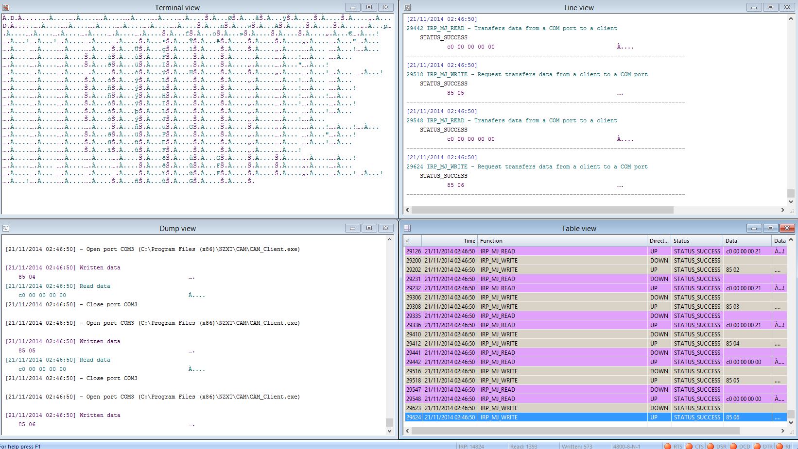
It was a binary protocol operating within 1-6 bytes of data per request/reply. The COM port operates at 4800 baud 8N1. I was able to map the protocol as follows :
| Command | Send (hex) | Recv (hex) |
| Initialization | C0 | 1F |
| Set FAN RPM 40% | 44 00 C0 00 00 06 00 | 01 |
| Set FAN RPM 45% | 44 00 C0 00 00 06 50 | 01 |
| Set FAN RPM 100% | 44 00 C0 00 00 0C 00 | 01 |
| Poll FAN1 RPM | 8A 01 | C0 00 00 [00 00] (uint16) |
| Poll FAN2 RPM | 8A 02 | C0 00 00 [00 00] (uint16) |
| Poll FAN3 RPM | 8A 03 | C0 00 00 [00 00] (uint16) |
| Poll FAN4 RPM | 8A 04 | C0 00 00 [00 00] (uint16) |
| Poll FAN5 RPM | 8A 05 | C0 00 00 [00 00] (uint16) |
| Poll FAN6 RPM | 8A 06 | C0 00 00 [00 00] (uint16) |
| Poll Total Voltage | 84 00 | C0 00 00 [00] [00] (uint8 uint8) |
| Poll FAN1 Amperage | 85 01 | C0 00 00 [00] [00] (uint8 uint8) |
| Poll FAN2 Amperage | 85 02 | C0 00 00 [00] [00] (uint8 uint8) |
| Poll FAN3 Amperage | 85 03 | C0 00 00 [00] [00] (uint8 uint8) |
| Poll FAN4 Amperage | 85 04 | C0 00 00 [00] [00] (uint8 uint8) |
| Poll FAN5 Amperage | 85 05 | C0 00 00 [00] [00] (uint8 uint8) |
| Poll FAN6 Amperage | 85 06 | C0 00 00 [00] [00] (uint8 uint8) |
The return values for the RPM polling commands are 2-byte unsigned values while the fan voltage and amperage polling commands return 2x single byte unsigned values. You’ll need to convert to decimal representation to get the values. For example :
POLL FAN1 RPM – C0 00 00 03 00 = 0x0300 = 768 rpm
POLL TOTAL VOLTAGE – C0 00 00 0B 01 = 0x0B 0x01= 11.01 volts
POLL FAN1 AMPERAGE – C0 00 00 00 19 = 0x00 0x19 = 0.25 amps
Wattage calculation is performed by taking the total voltage multiplied with fan amperage readout.
Writing My Fan Control Software for the GRID+
Within a couple of minutes of figuring out the protocol, I was able to quickly prototype a simple .NET application in Visual Studio 2013 to control and read values from the fan controller.

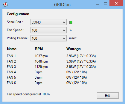
With serial port, fan speed and polling interval control, it uses about 0.1% CPU and 5MB+ of RAM while active (as opposed to the 1-30% CPU and 120MB+ resource usage of the original CAM software). The resource consumption of the software can further be lowered by increasing the polling interval with the downside being slower fan read/control times. It still needs CPU/GPU/ambient temperature readout which will allow for custom fan speed control curves — but I’m pretty happy with the software as it is.
If you’re using the NZXT GRID+ digital fan controller and are currently frustrated with the bundled software, the drivers, binaries and full VB .NET source code for my app can be downloaded here. Feel free to make any modifications you like so that the GRID+ hardware works better for you.